Saturday, September 14, 2013

TRANSITING THE PANAMA CANAL - Abhishek Sabharwal.

Hello everyone.....Good morning to all....
Over here in this post i will discuss a very practical experience in the Panama Canal along with some pics and videos based on my past experiences so as we can understand it as a whole.

The panama canal is a 77 kilometre ship canal in Panama that connects the Atlantic Ocean (via the Caribbean sea) to the pacific ocean and it saves the trouble of nearly a 12000 kilometres....i.e which would have been caused if the panama canal was not there and someone had to cross from the pacific to the Atlantic ocean via south of south America.....

Drawn below is a sketch of the Panama canal so as it can be understood in a better manner......


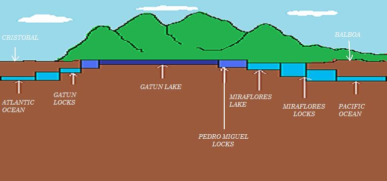
Approaches to the Panama canal

Pacific Ocean Entrance-----Port of Balboa--------Miraflores locks (2 chambers)-------Pedro Miguel locks (1 chamber)--------Gatun locks (3 chambers)-----Port of Cristobal------Atlantic Ocean.


Preparations for the vessel prior approaching


  • Ensure that the mooring winches and the windlass / anchor are all working in good condition.
  • Ensure mooring winches are primed beforehand tried and tested (as on certain ships).
  • Mooring ropes are in good condition.
  • All ships equipment including machinery/bridge equipments are in good working condition and any confessions regarding the non functioning of any equipment shall be truly done beforehand  to the          authorities so as to avoid unnecessary heavy fines/allegations/claims for delaying other vessels.
  • Another important thing is to ensure that no kind of structure is hanging out of the ship side as it might get damaged / or cause damage to the ship structure as the lock gate widths in the panama canal is very narrow...

Approaching the Panama Canal


  • Pilot is on board.
  • All concerned to be standby for stations.
  • Prepare pilot ladder as the panama canal crew will be boarding shortly.
  • At least 15-20 people board the ship depending on the size of the ship.
  • Keep a good headcount and a close track of the whereabouts of the people boarding the ship.
  • Mooring winches to be in a state of readiness.


  • Now the ship is brought alongside by the pilot.
  • Depending on the size of the ship wire ropes are passed by the canal crew on the ship basically 4 headlines and 4 stern lines.
  • These lines are then passed onto the Locomotives on the jetty which are high power mini trailers which using their strength pull the ship in/out  through the canal. (see fotos below).


  • Once the ship is pulled in by the locomotives , the lock gates are closed and water is ballasted (filled)  in ,
  • These locomotives keep the wires taught throughout so as the ship doesn't suffer any damages because of      any motion inside the lock while the ballasting process in on.
  • Once the ballasting process is done ,the lock gate ahead is opened as the water levels are now equal.
  • Now these locomotives pull the ship through.
  • Please note that as per the panama canal authorities, the ships engines are not to be used inside the locks        but can be used at times,depending on the circumstances / as per pilots instructions.

A ship transiting through the panama canal is the same process as a person travelling via an elevator or descalator in order to move up or move down.......So for a ship to climb up the canal every time water is ballasted (filled) in and gradually it climbs from one lock gate to the other and the reverse is the process when water is deballasted each time in each lock gate when the vessel moves down the canal.........

Attached below is a real time video made by me while i was transiting through the panama canal and i am sure that this video will make the picture of panama canal transit very clear in our minds......


But the entire experience of transiting the panama canal is superb as u get to see and learn a lot.
From the geographical point of view the place panama is an absolute jungle and is very dense.

The Panama Canal Locomotives


  • The original locomotives were manufactured by the "General Electric".
  • Also known by the names "mule" or "lock mule";
  • Electrically operated;
  • Have an approx. weight of 45-50 tonnes;
  • Maximum towing capacity of around 312 kilonewtone;
  • Have an average towing speed of 5~8miles an hour;
  • The locomotive traffic has increased in the passing years , on account of increasing shipping traffic and demand of more & more vessels passing through the panama canal.
  • They run on a specially constructed steel track and have a 12 gear base which provides them great stability. 


Attached below is another interesting video of "The Panama Canal Locomotive" operation towing the ship i was sailing on.....


Increasing the size of the Panama Canal, was a much awaited thing to be done as the increasing number and the increasing sizes of the new age ships demanded the same.In the year 2007 , a 5.2 billion dollar project was introduced to expand the canal.The work is extensively in progress and the expected completion is in the early months of the year 2015.

Undoubtedly this expansion will be of a huge potential significance to U.S trade routes,shippers,railways,truckers,manufacturers,U.S supply chains,logistics companies,owners of industrial and residential real estates as well as investors.

Your opinions / comments / feedbacks / queries are most invited....thanks for stoppingby....
cheers......

Abhishek Sabharwal.....

(Please note , that all of the photgraphs and videos as shown above , originally belong to me and i owe the copyright to all of them)

Sunday, September 1, 2013

HOW TO ADD A PAGE TO YOUR BLOG - Abhishek Sabharwal

HOW TO ADD A PAGE TO YOUR BLOG

Overhere in this post we will try and learn as to how to add a page to our blog in a step by step process so as no mistakes are done........

STEP 1.
Login to your blogger account using your registered email id and password.

STEP 2.
Go to your blogger dashboard.

STEP 3.

Click on the 'NEW PAGE" tab as shown below..........


STEP 4.

Now click on "blank page"........


STEP 5.

Such a page opens up as shown below.....And now you can create the page with whatever title you want for your blog as in the case below it is the "contact me" page....


STEP 6.

Additionally , the page can be adjusted on the blog as wished by you, in the manner as shown below.....
Top tabs: Allows the page section to be shown right on top below your blog title or as designed by your                       blogs template.
Side tabs: Allows the page section to be positioned in the side bar or as designed by your blogs template.


STEP 7.

This is how it looks like.....


I hope it was helpful.........
For any further doubts/queries....please do contact me.....thanks for your interest.....cheers.......
happy blogging......


Friday, August 2, 2013

MARKING ABORT POINTS - Abhishek Sabharwal

Overhere we will learn the correct procedure for marking of abort points on the chart while preparing a passage......This again seems to be a topic which is of concern , as many people onboard are unaware of the correct thing.

DEFINING AN ABORT POINT :


An abort point or a point of no return , is a point beyond which the vessel is bound to follow a passage and there is no way to look back.This might be because of  factors like , converging of land somewhere along the passage of the vessel which might severely restrict the manoeuvrability of the  vessel to turn back because of very less room and thereby insist her to proceed in the direction of the traffic flow.


HOW TO DECIDE WHERE TO MARK AN ABORT POINT ALONG THE PASSAGE :


The governing factor for determining the location of the abort point is the turning circle of the ship.

From your vessels manoeuvring diagram , determine the value of advance / transfer.

Assuming that the values as obtained by you are

Advance: 0.40 nm.
Transfer: 0.65 nm.

Please find the sketch below to understand better......


ABORT POINT

Additionally please understand that as a good practise of seamanship and as an important thing by virtue is to always try out engines ,well before the abort point so as the navigator is sure that his engines are working in good order.


Note :

Some people have the misconception , that only one abort point can be marked in a passage,which is a wrong thought.
It is possible that vessels along their passage might encounter narrow passages at more than one occasions and as a good and essential practise it is required to mark an abort point and additional actions and precautions taken accordingly. 


Thursday, August 1, 2013

HOW TO SET ECDIS SAFETY PARAMETERS = SAFETY DEPTH + SHALLOW CONTOUR - Abhishek Sabharwal

SAFETY DEPTH / SAFETY CONTOUR:

Safety depth is considered to be the minimum depth required in which the vessel can safely navigate and any depths lower than that might compromise the safety of the vessel.For all practical purposes the safety depth is determined as follows;

M.V ABCD
Draft (static) - 12.5 mtrs
Speed - 10 kts
Assuming block coefficient : 0.7 (to simplify things)

Squat (for confined waters): Cb x V(Square) / 50
                                         = 0.7 x 10 x 10 / 50 = 1.40 mtrs.

Assuming Height of Tide: 1.4 mtrs

Ukc (required as per individual company policy) : 20 % of static draft (in coastal waters)
                                                                               = 20 x 12.5 / 100 = 2.5 mtrs.
  Safety Depth :
   = Draft + Squat + Ukc - Ht. of Tide
   = 12.5 + 1.40 + 2.5 - 1.4 = 15.0 mtrs.  

SHALLOW DEPTH / SHALLOW CONTOUR :

Shallow depth setting is considered to be the grounding depth i.e the vessel will run aground at that depth.

Therefore,for all practical purposes, the shallow depth is considered to be draft of the vessel.
i.e Draft=12.5 mtr then Shallow depth=12.5 mtr.

Shallow depth=12.5 mtr;

Nearest available contour=15mtr (as there are no 12.5 mtr contours).

Which implies that when the shallow depth is set to 12.5 mtrs(~~15.0 mtrs) then all the areas falling inside this depth range will turn into dark blue colour, thus reminding the navigator of its shallow nature.

Lets see an example as to how does such a setting affect the appearance of an ECDIS chart.....

BEFORE (SHALLOW CONTOUR =0)


AFTER (SHALLOW CONTOUR=15.0 MTR)


DEEP CONTOUR:

Whereas Deep contour for all practical purposes is considered as a contour depth at which the shallow water effects might start having an effect on the manoeuvrability of the ship, which is taken as

Deep Contour: 4 x draft of the vessel (standard accepted value)
i.e Draft=12.5 mtr ; Deep contour=4x12.5= 60 mtrs.

SPOT SOUNDINGS:

 Spot soundings doesnt form a mandatory requirement of an ECDIS feature and thereby is just an additional feature which might be found on certain ECDIS make types such as TRANSAS.

If the spot sounding on an ECDIS is set to , say 60mtrs,then all depths on the chart greater 60 mtrs will get dissapeared and all those less than equal to 60 mtrs will be displayed in `bold` on the chart, as shown below.The main purpose of spot soundings is to eliminate clutter or unnecessary information from the chart in terms of depths.

BEFORE (SPOT SOUNDING=0 MTRS)


AFTER (SPOT SOUNDING = 60 MTRS)


In the above figure we can clearly see that how setting a spot sounding removes unnecessary depths from the chart thereby reducing chart clutter.


NOTE:


It is very important to understand that the settings of the above stated parameters is  very important as it causes the safety frame/guard zone to trigger alarms for the vessel while entering these depths.Which implies that if these settings are not correct then no alarms will be triggered or will not be triggered in time, and which might lead to catastrophic results.


I would like to know any of ur comments / suggestions / queries if any......tk cre..cheers...
Thanks for stoppingby......:)


Wednesday, July 31, 2013

HOW TO MARK NO GO AREAS - Abhishek Sabharwal

Marking No Go Areas is a task , which over a period of time , I have realised is a job which most of the second officers are not clear about (no offences/disrespect to anyone).
This inefficiency leads to charts being incorrectly marked (Let it be on an ECDIS or Paper chart) and the other duty officers in turn assume that the markings are correct,which is not the case.
So today we will identify the rights and wrongs of No Go Areas thereby covering the common mistakes done by everyone and the right procedure to do it.

No Go Area:

A  no go area is an area where the vessel cannot /should not go, as that is dangerous because of a shallow nature or any other surface / sub surface obstruction identified as dangerous to navigation for seagoing ships or any other condition which can compromise the safety of the vessel.

CALCULATIONS:

We will take the example of a vessel at sea and then try to understand the concept,

M.V ABCD
Draft (static) - 12.5 mtrs
Speed - 10 kts
Assuming block coefficient : 0.7 (to simplify things)

Squat (for confined waters): Cb x V(Square) / 50
                                         = 0.7 x 10 x 10 / 50 = 1.40 mtrs.

Assuming Height of Tide: 1.0 mtrs

Ukc (required as per individual company policy) : 20 % of static draft (in coastal waters)
                                                                               = 20 x 12.5 / 100 = 2.5 mtrs.
Depth Required for the vessel to stay safe: (criteria for marking no-go areas)
   = Draft + Squat + Ukc - Ht. of Tide
   = 12.5 + 1.40 + 2.5 - 1.0 = 15.40 mtrs.

MYTH:

A typical myth followed by lot of people on ships is , that the shallow pattern coloured areas (light blue) near a coastline are the lines joining no go areas and on most of the ships it is observed that people mark the entire light blue shaded portion on charts as no go areas near the coast , which is wrong and is a PSC deficiency and these no go shade lines are even extended onto the coast itself.

WRONG METHOD :


RIGHT METHOD :

The right way to do it, is to calculate the safety depth as calculated above and  all depths below this depth are considered to be as no go depths i.e depths below which it is considered unsafe for the vessel to navigate.
As in our case the safety depth as calculated is 15.4 mtrs and the nearest rounded off depth is 16 mtrs.Thereby, on the chart join all depths of 16mtrs. Now shade off the entire area between the coast and the line as explained above. Mark this area as a no go area.

Note: 

Please make a note of the fact that the marking of a no go area is a dynamical calculation i.e it varies with the variation in various parameters such as draft, ukc,vessel speed, height of Tide prevailing at that time


Hope the above explanation serves the purpose......For any suggestions / queries / comments ur most invited.....Thanks for stopping by........cheers....

Monday, July 29, 2013

ENC DATA COLLECTION CHART - Abhishek Sabharwal


  • NHO`s are National Hydrographic Organisations.
  • RENC`s are Regional Electronic Navigation Chart Systems.
  • Whereas CMAP,TRANSAS,MARINE PRESS are the main distributors.
  • Lets understand the above chart , IHO is the governing authority under which the NHO`s of various countries are working.These NHO`s , survey and collect their own data and send it to the RENC`s i.e UKHO,PRIMAR which in turn compile these datas,process them and then distribute it to the respective distributors which in turn sell those charts to us on ships.

Any suggestions/comments are most invited......
Cheers....


Sunday, July 28, 2013

LIFEBOAT ACCIDENT - Abhishek Sabharwal

Today , ill share one of my bad experiences which involve a lifeboat accident.I was on a Panamax size bulk carrier which was at anchor.I was a trainee those days and I had a crooked master and a very nice mate.

It was around 3 in the afternoon,weather was  a bit windy ,force 4 and a swell of around 1.5 meter , when the Master of the ship all of a sudden realised that he wants to conduct a drill.

Despite of the fact that the chief mate didnt want to lower the lifeboat under such circumstances and neither of the crew members wanted to do the same,still all of us forcefully had to lower and launch the boat because of the masters decision.Just pissed from the decision all concerned parties reluctantly commenced preparing and consequently lowered the lifeboat into the water with the master,bosun,3rd officer,one os on the top and chief mate,me,ab,3rd engineer,second officer in the boat.The VTS had been duly reported.

We reached the water level,tried out engines, and were consequently released the hooks but while releasing the aft hook the A.B just saved his head because of the heaving motion of the boat the aft fall block almost hit his head.Once waterborne, the lifeboat started heaving badly and that day i actually realised ,what a 1.5 mtr swell looks like...hehe...

Lifeboat engines were started and we moved away from the ship.....she was pitching very badly and everyone in the boat ,staring at each others faces were cursing the master....all of us starting vomiting all over as its a normal human tendency....no one could resist that feeling...We moved a few metres away from the ship and then we realised that a ship was passing by at a distance of around 5 cables and because of the size of the wake of the ship (which was moving towards us) we decided to move back towards our ship.

We tried turning back but couldnt as she started behaving abruptly because of the following factors....wake of the other ship,wind,swell....so we decided that we will tell our bosun who was on the lifeboat deck to throw a gantline to us for our assistance.Following which , he did threw a gantline at us (Somehow!!!) , and we secured the same to our boat but left a lot of slack in the water , which the bosun did not pull in time and the chief mate without checking that the propellers are clear or not started the boats engine with a full ahead and within seconds the propeller blades and the shaft itself got absolutely entangled with the gantline. Hence, now to make situations worse we didnt had our engines either and we were still fighting with the tremendous heaving motion of the boat....With  alot of efforts of the ships crew on deck they managed to pull us alongside to some extent using mooring winches and what not....As we were approaching towards our own ship....we realised that because of the push of the wind and the waves we approaching at a fast rate towards our ship and hell broke loose on us....

We banged hard into the ship-side thereby producing a crack to the portside of our boat, and our immediate reaction was to use our boat hooks to push away , and then boat oars but all of our efforts went in vain....and we landed up with broken oars,cracked boat,and broken boat hooks....to make situations worse we further started moving into the rudder and were banging continuously to the ship side.....

Again a gantline was passed and we just managed to fall right below the fall blocks following again a series of hardwork ,ideas,efforts we were pulled up and the boat stowed.Later on a accident report was prepared all crew members briefed and was a learning lesson for the master and the other members of the ship.

Unfortunately i dont have those interesting lifeboat damage fotos available , but ill surely search for them and will post them in due time.....


Despite of so much of awaeness onboard and in being a very proactive industry i just dont understand as to why people ,even today dont understand the meaning of the word "SAFETY"......???


Please send me your valuable feedback or any suggestions / comments on the above topic....

"BON VOYAGES"....

Thursday, July 25, 2013

WHAT ARE SHIP SECURITY LEVELS ? - Abhishek Sabharwal

SECURITY LEVEL 1

At security level 1,the SSP (Ship Security Plan) should establish the security measures to control access to the ship ,where the following may be applied ;

  • checking the identity of all the persons seeking to board the ship and confirming their reasons for doing so by checking, for example,joining instructions,passenger tickets,boarding passes,work orders etc;
  • in liason with the port facility the ship should ensure that designated secure areas are established in which inspections and searching of persons, baggage,personal effects,vehicles and their contents can take place;
  • in liason with the port facility the ship should ensure that vehicles designed to be loaded onboard car carriers,ro ro and other passenger ships are subjected to search prioe to loading ,in accordance with the frequency required in the SSP;
  • segregrating checked persons and their personal effects from unchecked persons and their personal effects;
  • segregating embarking from disembarking passengers;
  • identifying access points that should be secured or attended to prevent unauthorized access;
  • securing by locking or other means,access to unattended spaces adjoining areas to which passengers or visitors have access,and;
  • providing security briefings to all ship personnel on possible threats,the procedures for reporting suspicious persons ,objects or activities and the need for vigilance.

SECURITY LEVEL 2

At security level the SSP should establish the security measures to be applied to protect against  a hightened risk of a security incident to ensure higher vigilance and tighter control,which may include,

  • assigning additional personnel to patrol deck areas during silent hours to deterr unauthorised access;
  • limiting the number of access points to the ship,identifying those to be closed and the means of adequately securing them;
  • deterring waterside access to the ship including;
  • establishing a restricted area on the shore sideof the ship,in close co-operation with the port facility;
  • increasing the frequency and detail of searches of persons ,personal effects and vehicles being embarked or loaded onto the ship;
  • escorting visitors on the ship;
  • providing additional specific security briefings to all ship personnel on any identified threats , reemphasizing the procedures for reporting suspicious persons,objects or activities and stressing the need for increased vigilance;
  • carrying out a full or partial search of the ship.

SECURITY LEVEL 3

At security level 3 the ship should comply with the instructions issued by those responding to the security incident or threat thereof.The SSP should detail the security measures which could be taken by the ship , in close coperation with those responding and the port facility,which may include,

  • limiting access to a single,controlled access point;
  • granting access only to those responding to the security incident or threat thereof;
  • directing persons onboard;
  • suspension of embarkation or diembarkation;
  • suspension of cargo handling operations,deliveries,etc;
  • evacuation of the ship;
  • movement of the ship;
  • preparing for a full or partial search of the ship. 


DECLARATION OF SECURITY (DOS) - Abhishek Sabharwal

- Contracting governments shall determine when a Declaration of Security is required by assessing the risk        the ship/port interface or ship to ship activity poses to persons,property or the environment.
- A ship can request completion of a declaration of security when:

  • the ship is operating at a higher security level than the port facility or another ship it is interfacing with;
  • there is an agreement on a DOS between contracting governments covering certain international voyages or specific ships on those voyages;
  • there has been a security threat or a security incident involving the ship or involving the port facility ,as applicable;
  • the ship is at a port which is not required to have and implement an approved port facility security plan; or
  • the ship is conducting ship to ship activities which another ship not required to have and implement an approved ship security plan.  
- Requests for the completion of a declaration of security , under this section shall be acknowledged by the      applicable port facility or ship.
- The DOS shall be completed by :
  •    the master or the ship security officer on behalf of the ship(s); and if appropriate ;
  •    the port facility security officer or,if the contracting government determines otherwise , by any other      body responsible for shore side security, on behalf of the port facility.
- The D.O.S shall address the security requirements that could be shared between a port facility and a ship (or between ships) and shall state the responsibility of each.


Attached below is a sample DOS as extracted from the ISPS Code (Appendix 1 Part B) :

DECLARATION OF SECURITY FORM

As provided in Appendix 1, Part B of the ISPS Code


Name of ship:....................................................................................................................

Port of registry:..................................................................................................................

IMO Number:.....................................................................................................................

Name of Port Facility:.......................................................................................................

This Declaration of Security is valid from ………. until ………. for the following activities: (list the activities with relevant details)

.............................................................................................................................................

.............................................................................................................................................

.............................................................................................................................................

.............................................................................................................................................

Under the following security levels:

Security level(s) for the ship:.......................................................................................
Security level(s) for the Port Facility:.........................................................................

The Port Facility and ship agree to the following security measures and responsibilities to ensure compliance with the requirements of Part A of the International Code for the Security of Ships and of Port Facilities.


The affixing of the initials of the PFSO or the SSO under these columns indicates that the activity will be done, in accordance with the relevant approved plan, by
Activity
The Port Facility
The ship
Ensuring the performance of all security duties


Monitoring restricted areas to ensure that only authorised personnel have access


Controlling access to the Port Facility


Controlling access to the ship


Monitoring of the Port Facility, including berthing areas and areas surrounding the ship


Monitoring of the ship, including berthing areas and areas surrounding the ship


Handling of cargo


Delivery of ships stores


Controlling the embarkation of persons and their effects


Ensuring that security communication is readily available between the ship and the Port Facility


The signatories to this agreement certify that security measures and arrangements for the Port Facility and ship required by part A of the ISPS Code will be implemented in accordance with the provisions stipulated in their approved plan. Where other, specific arrangements have been agreed these are set out in the attached document.
Signed for and on behalf of
The Port Facility:


(Signature of PFSO)
The ship:


(Signature of Master or SSO)
Name and title of person who signed
Name:

Name:

Title:

Title:

Contact details
(to be completed as appropriate, indicate telephone numbers, radio channels or frequencies to be used)
Port Facility
Ship
PFSO
Master
Ship supervisor
Duty Officer

SSO

Company

CSO


SENC INFORMATION AVAILABLE FOR DISPLAY DURING ROUTE PLANNING AND ROUTE MONITORING - Abhishek Sabharwal

DISPLAY BASE

- coastline (high water);
- own ship`s safety contour;
- isolated underwater dangers of depths less than the safety contour which lie within safe waters defined by      the safety contour;
- isolated dangers which lie within the safe water defined by the safety contour, such as fixed structures ,          overhead wires ,etc;
- scale,range and north arrow;
- units of depth and height ;and
- display mode.

STANDARD DISPLAY

- display base;
- drying line;
- buoys,beacons,other aids to navigation and fixed structures;
- boundaries of fairways,channels,etc;
- visual and radar conspicuous features;
- prohibited and restricted areas;
- chart scale boundaries;
- indication of cautionary notes;
- ship`s routeing systems and ferry routes;
- archipelagic sea lanes.

ALL OTHER INFORMATION TO BE DISPLAYED INDIVIDUALLY ON DEMAND,(FOR EXAMPLE)

- spot soundings;
- submaine cables and pipelines;
- details of all isolated dangers ;
- details of aids to navigation;
- contents of cautionary notes;
- ENC edition date;
- most recent chart update number;
- magnetic variation;
- graticule;
- place names.

NOTE OF PROTEST - Abhishek Sabharwal


14.  NOTE OF PROTEST

A “Note of Protest” is basically a declaration formally recorded or lodged by the Master of circumstances beyond his control which may give, or may have given, rise to loss or damage. In other words, Notes of Protest are lodged to record occurrences that may have caused loss or damage which are at that moment unknown or not fully determinable or quantifiable but could give rise to claims at a later date, e.g., shifting damage to cargo which cannot be accessed until over-stowing cargo is discharged, the possibility of sweat damage to cargo because of not being able to follow prescribed ventilation procedures due to adverse weather conditions, possible pounding or panting damage to the ship’s hull that may remain unknown until sighted a next dry docking, possible damage due to the vessel suspected to have “bottomed” during a river / shallow water transit, etc. Such declaration must be made before a notary public, magistrate or other authority. In many ports, the agents can lodge the Note of Protest on behalf of the Master.

A Note of Protest must generally be lodged within 24 hours of arrival port, but if this is not possible the Master may add a statement in the Note of Protest to the effect that the Note of Protest could not be tendered earlier due to circumstances beyond the Master’s control.

The following list, enumerates some of the circumstances in which a master should note protest.

14.1     “Whenever the vessel has encountered heavy weather which might have resulted in damage to the cargo or the ship.

14.2     WHEN FROM ANY CAUSE THE SHIP IS DAMAGED, or there is reason to fear that damage may be sustained.

14.3     When through stress of weather it has not been practicable to adopt normal precautions in the matter of Ventilation of perishable cargo.

14.4     When any serious breach of C/P terms is committed by the Charterer or his agent, such as refused to load, unduly delaying loading, loading improper cargo, refusal to pay demurrage, refusal to accept B(s)/L in the form signed by the master etc.  (IN SHORT, ANY MAJOR PROBLEM WITH CARGO, C/P OR B/L.)

14.5     When cargo is shipped in such condition that it is likely to suffer deterioration during the voyage.  In this case however the protest will not be effective unless the B/L was endorsed to show the condition of the cargo at the time of shipment.

14.6     In all cases of general average.


14.7     In case stevedores refuse to accept a damage report.

Notes of protest must be supported by appropriate log entries, and if required, with statements from the master and others.

In certain countries the note of protest has to be made on a special form.  Always seek assistance of the local agents to find out the correct procedure.

A note of protest may need to be extended as at the time when a protest is originally noted it may not have been definitely established whether in fact loss or damage has occurred or not or the full extent of damage may not be known.

SENC (SYSTEM ELECTRONIC NAVIGATIONAL CHART) - Abhishek Sabharwal

In order to get efficient data structures that facilitate the rapid display of ENC data,most ECDIS convert
each ENC dataset from S-57 into an internal machine language format called SENC or System ENC - which is optimised for chart image creating routines. Each ECDIS software manufacturer has its own SENC format.Consequently the SENC format may differ between ECDIS manufacturers.

WHAT ARE OFFICIAL CHARTS IN ECDIS ? - Abhishek Sabharwal

What are official charts?
According to SOLAS V (see page 7) , charts issued by or on the authority of a Government ,authorized Hydrographic Office or other relevent government institutions are official and may be used to fulfill carriage requirements (provided they are kept uptodate).

All other nautical charts are by definition not official and are often referred to as unofficial or private charts.These charts are not accepted as the basis for navigation under the SOLAS Convention.

There are two kinds of official digital nautical charts commonly available ; Electronic Navigational Charts (ENC) and Raster Navigational Charts (RNC).

VHF / MF DSC DISTRESS ALERT - Abhishek Sabharwal


RASTER AND VECTOR CHARTS - Abhishek Sabharwal

DIFFERENCES BETWEEN RASTER AND VECTOR CHARTS

                           RASTER                                                                          VECTOR
- Entire chart is stored as one single layer i.e        - Information is stored in layers and hence can be
  information stored cannot be displayed                 displayed selectively.
  selectively.
- Customization is not possible.                            - Chart can be designed as per the request of the user i.e
                                                                              customization is possible.
- Direct copy of a paper chart.                             - Computer generated chart.
- Chart appers cluttered.                                      - Cluttering of chart can be avoided.
- Information can only be added.                          - Information canm be added and subtracted.
- Interrogation for more information is not             - Interrogation for more information is possible.
   possible.
- Seamless charts not possible.                              - Seamless chart is a feature.
- Sensible rotation to any angle, like head up          - Possible.
   is not possible.
- Display generation takes time.                             - Faster.
- Safety departments , entering TSS etc.                - Possible.
   alarms not possible.
- Symbols and colours as that of a paper chart.      - As per IHO publication.
- Scale cannot be changed.                                    - Different scales possible.
- Zooming facility not possible.                               - Possible.
- Cheaper to produce.                                            - Costly / time consuming.
- Worldwide coverage available.                           - Coverage for all trading routes achieved.
- Memory required is higher.                                   - Memory required is comparatively less.
- This is used an interim to vector charts and           - With developement of ENC , charts will be phased
   only when ENC is not available.                                out very soon.
- Since chart is in a single layer ,no information         - Loss of information is possible and a visual indication    can be lost.                                                               is given.