Overhere we will learn the correct procedure for marking of abort points on the chart while preparing a passage......This again seems to be a topic which is of concern , as many people onboard are unaware of the correct thing.
DEFINING AN ABORT POINT :
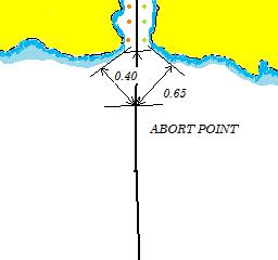
An abort point or a point of no return , is a point beyond which the vessel is bound to follow a passage and there is no way to look back.This might be because of factors like , converging of land somewhere along the passage of the vessel which might severely restrict the manoeuvrability of the vessel to turn back because of very less room and thereby insist her to proceed in the direction of the traffic flow.
HOW TO DECIDE WHERE TO MARK AN ABORT POINT ALONG THE PASSAGE :
The governing factor for determining the location of the abort point is the turning circle of the ship.
From your vessels manoeuvring diagram , determine the value of advance / transfer.
Assuming that the values as obtained by you are
Advance: 0.40 nm.
Transfer: 0.65 nm.
Please find the sketch below to understand better......
Additionally please understand that as a good practise of seamanship and as an important thing by virtue is to always try out engines ,well before the abort point so as the navigator is sure that his engines are working in good order.
Note :
Some people have the misconception , that only one abort point can be marked in a passage,which is a wrong thought.
It is possible that vessels along their passage might encounter narrow passages at more than one occasions and as a good and essential practise it is required to mark an abort point and additional actions and precautions taken accordingly.
Friday, August 2, 2013
Thursday, August 1, 2013
HOW TO SET ECDIS SAFETY PARAMETERS = SAFETY DEPTH + SHALLOW CONTOUR - Abhishek Sabharwal
SAFETY DEPTH / SAFETY CONTOUR:
Safety depth is considered to be the minimum depth required in which the vessel can safely navigate and any depths lower than that might compromise the safety of the vessel.For all practical purposes the safety depth is determined as follows;
M.V ABCD
Draft (static) - 12.5 mtrs
Speed - 10 kts
Assuming block coefficient : 0.7 (to simplify things)
Squat (for confined waters): Cb x V(Square) / 50
= 0.7 x 10 x 10 / 50 = 1.40 mtrs.
Assuming Height of Tide: 1.4 mtrs
Ukc (required as per individual company policy) : 20 % of static draft (in coastal waters)
= 20 x 12.5 / 100 = 2.5 mtrs.
Safety Depth :
= Draft + Squat + Ukc - Ht. of Tide
= 12.5 + 1.40 + 2.5 - 1.4 = 15.0 mtrs.
SHALLOW DEPTH / SHALLOW CONTOUR :
Shallow depth setting is considered to be the grounding depth i.e the vessel will run aground at that depth.
Therefore,for all practical purposes, the shallow depth is considered to be draft of the vessel.
i.e Draft=12.5 mtr then Shallow depth=12.5 mtr.
Shallow depth=12.5 mtr;
Nearest available contour=15mtr (as there are no 12.5 mtr contours).
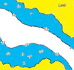
Which implies that when the shallow depth is set to 12.5 mtrs(~~15.0 mtrs) then all the areas falling inside this depth range will turn into dark blue colour, thus reminding the navigator of its shallow nature.
Lets see an example as to how does such a setting affect the appearance of an ECDIS chart.....
BEFORE (SHALLOW CONTOUR =0)
AFTER (SHALLOW CONTOUR=15.0 MTR)
DEEP CONTOUR:
Whereas Deep contour for all practical purposes is considered as a contour depth at which the shallow water effects might start having an effect on the manoeuvrability of the ship, which is taken as
Deep Contour: 4 x draft of the vessel (standard accepted value)
i.e Draft=12.5 mtr ; Deep contour=4x12.5= 60 mtrs.
SPOT SOUNDINGS:
Spot soundings doesnt form a mandatory requirement of an ECDIS feature and thereby is just an additional feature which might be found on certain ECDIS make types such as TRANSAS.
If the spot sounding on an ECDIS is set to , say 60mtrs,then all depths on the chart greater 60 mtrs will get dissapeared and all those less than equal to 60 mtrs will be displayed in `bold` on the chart, as shown below.The main purpose of spot soundings is to eliminate clutter or unnecessary information from the chart in terms of depths.
BEFORE (SPOT SOUNDING=0 MTRS)
AFTER (SPOT SOUNDING = 60 MTRS)
In the above figure we can clearly see that how setting a spot sounding removes unnecessary depths from the chart thereby reducing chart clutter.
NOTE:
It is very important to understand that the settings of the above stated parameters is very important as it causes the safety frame/guard zone to trigger alarms for the vessel while entering these depths.Which implies that if these settings are not correct then no alarms will be triggered or will not be triggered in time, and which might lead to catastrophic results.
I would like to know any of ur comments / suggestions / queries if any......tk cre..cheers...
Thanks for stoppingby......:)
Subscribe to:
Posts (Atom)


